This example code should explain the basic bare metal program in assembly language. It can be used on many ARM Cortex M processors from M0 to M7 and from different manufacturers. Not just ST Microelectronics. This is because current example is so simple right now. I have plans to test and port this tutorials also on TI TIVA (former Stellaris, former LuminaryMicro) , NXP LPC processors.
You can get the code also on my Github https://github.com/hubmartin/ARM-cortex-M-bare-metal-assembler-examples/
Lets create and compile basic program that just increments number in R0 register. Content of main.S assembler file:
@ Vector table start
.long               0x20001000
.long               _start
@ Vector table end

_start:

loop:
    ADD R0, R0, #1
b loop

.global _start
On ARM Cortex devices there is a vector table which starts at the first byte in the program memory. Each vector is one word/32 bits long. that means 4 bytes for every item in this table. In this examples I have just two vectors/values defined by word “.long”. The first vector is special. It contains initial stack pointer address and this value is copied to the Stack Pointer “SP” register. In this example I am using just register R0 and there is no need for stack or memory at all. So to keep things simple let’s put here some address in memory area for now and move to the second vector. Second vector is called the Reset vector. On this position there’s an address of the very first instruction the MCU has to execute. So this value is copied to the Program Counter register. By suppling this “.long” with name “_start” I am specifying that the code should start execute at label “_start:” There can be other vectors like interrupts but since we don’t need them we can ignore that fact right now.
Now let’s increment register R0. ARM don’t have inc instruction like AVRs have. I have to use ADD instruction. So the instruction does that it takes number in R0 (the middle parameter), adds value #1 and saves it back to the same register R0 (first R0 argument).
Then there is simple branch instruction “b” which is calling our main loop loop called “loop:” :) Loop The “.global _start” says that the _start label/function should be exported and be visible by other code files and linker. The “_start” is default label in gcc. If you would like different label then you have to add –entry parameter to linker with your own name.
Compilation
I have created very basic Makefile
all: main.bin

main.o: main.S
    arm-none-eabi-as -mthumb -o main.o main.S

main.elf: main.o
    arm-none-eabi-ld -Ttext 0x8000000 main.o -o main.elf

main.bin: main.elf
    arm-none-eabi-objcopy -S -O binary main.elf main.bin
    arm-none-eabi-size main.elf

clean:
    rm main.elf main.o main.bin a.out
As first main.S is compiled by gcc assembly “as” program. It creates main.o file. Then this file should be linked. Linker “moves” the addresses in my assembly labels to the real memory space which for STM32 is at 0x8000000. That’s why there is -Ttext parameter. This can be done also with linker script but my solution makes things more simple right now. The term “text” for our code is there for historical reasons because in the early days “text” section was used for code that doesn’t change. Sections .data and .bss are for memory, but that would be covered in later tutorials.
After linking I get main.elf file. This is still object file with possible debug informations in it and it cannot be directly flashed to the MCU. I have to make binary file from that ELF file in the last step.
Also there is “size” utility which shows me how big the program is. Let’s try to call make:
arm-none-eabi-as -mthumb -o main.o main.S
arm-none-eabi-ld -Ttext 0x8000000 main.o -o main.elf
arm-none-eabi-objcopy -S -O binary main.elf main.bin
arm-none-eabi-size main.elf
   text    data     bss     dec     hex filename
     12       0       0      12       c main.elf
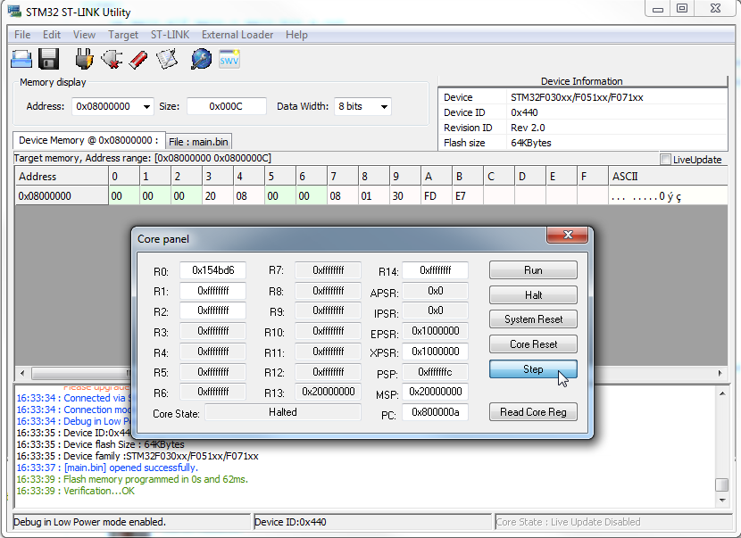
My increment application has only 12 bytes, sweet. There is also no RAM used, that’s why there is value zero at “data” and “bss” sections. In Windows you can flash your program to some STM32F0 discovery boards by ST-link utility. Then in the Menu > Target > MCU Core… you can single step my little program and you will see that R0 is really incrementing.
If you have OpenOCD / GDB connection, use commands below to test the program. Just remember to upload the main.elf file. Command “si” is step one instruction. We have to execute two instruction because one of them is increment (ADD) and the other branch instruction.
(gdb) load main.elf
Loading section .text, size 0xc lma 0x8000000
Start address 0x8000008, load size 12
Transfer rate: 35 bytes/sec, 12 bytes/write.
(gdb) info reg r0
r0             0x9792b7 9933495
(gdb) si
(gdb) si
(gdb) info reg r0
r0             0x9792b8 9933496
(gdb)
The increment program can be even smaller with just 8 bytes. It’s a dirty hack but since my main loop has exactly 4 bytes and I am not using the stack and first vector. I can stuff my instructions there! :)
_start:
loop:
    ADD R0, R0, #1
b loop

.long               _start
.global _start