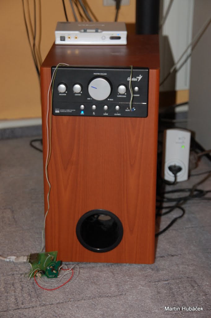
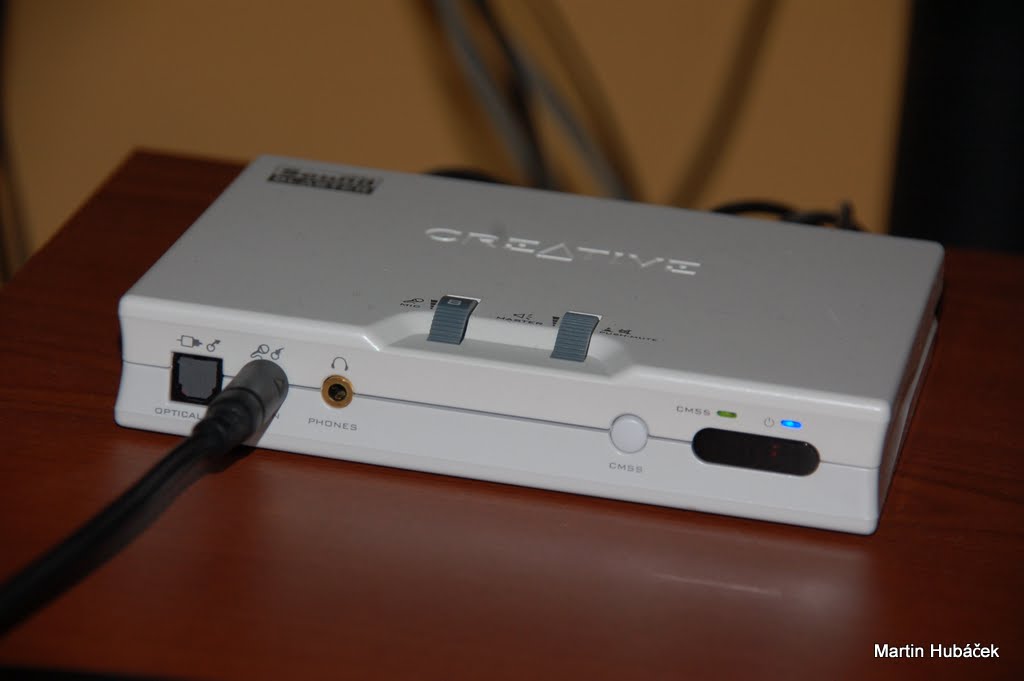
I use the Genius SW-HF 5.1 5005 speakers with my laptop. The speakers are good for my needs but also have some drawbacks. The woofer is making really really silent but annoying 50Hz hummm sound when is in standby mode and as I discovered last week, the speakers are eating a lot of power even in the stand-by mode, about 40W ! The transformer inside is so hot in stand-by that I cannot hold my hand on it.
I was planning a few upgrades for this speaker long time. Finally some other hackers analysed protocol for my radio controlled home plugs and my dream was even easier to accomplish :)
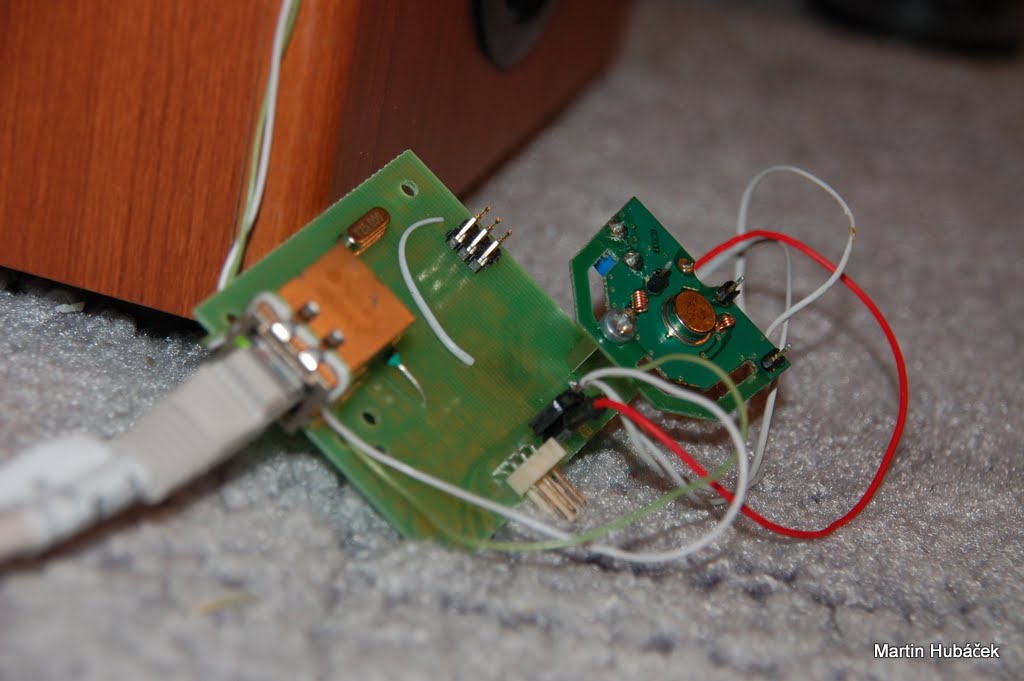
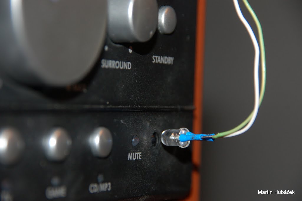
So I need to completely disconnect speakers from the mains when I don’t need them. I’m not comfortable with finding the main hardware switch somewhere on the back of the woofer under the desk. Also when I plug the speakers into the wall-plug. I have to turn them on by the button on the front side or use the IR remote control. So I have to simulate pressing of the buttons too somehow. I’ve decide to simulate infra red remote control to control the speakers. In repair-manual there’s also mentioned SPI bus inside the speakers, but there’s no difference if I have to analyse SPI commands or infra commands. Moreover I can reuse the IR emitter to control not only speakers but also my TV and DVB-T receiver…
The final code is here:
Oscilloscope
Thanks to Europe Union my RIGOL scope was delayed more than month, sitting somewhere on the post Prague 120 just because they changed some customs law but that’s much more complicated than this project and totally different story.. Great move! So it’s time for sound-card poor-man’s scope.. much more exciting :)
First of all, I’ve investigate the protocol of the remote. Since I had only reverse-voltage destroyed SFH-5110 infrared decoders, I took some panel from old VHS and that helped to demodulate the signal :)
And my scope look-liked this
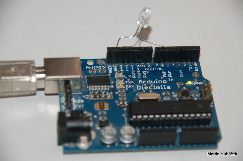
IR transmitter
Here’s the infrared protocol of Genius SW-HF 5.1 5005 speakers. The IR protocol is quite easy. Because there’s only a few buttons I don’t care what each bit does and I save the whole IR burst into my library. There’s probably some padding or CRC but I don’t care ;)
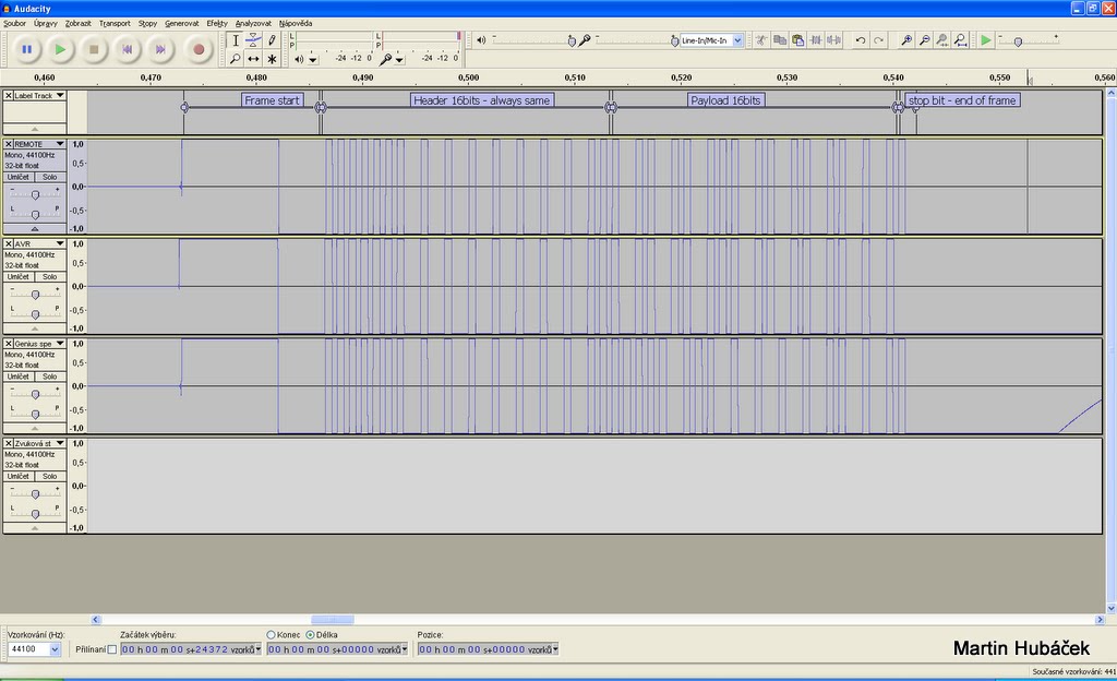
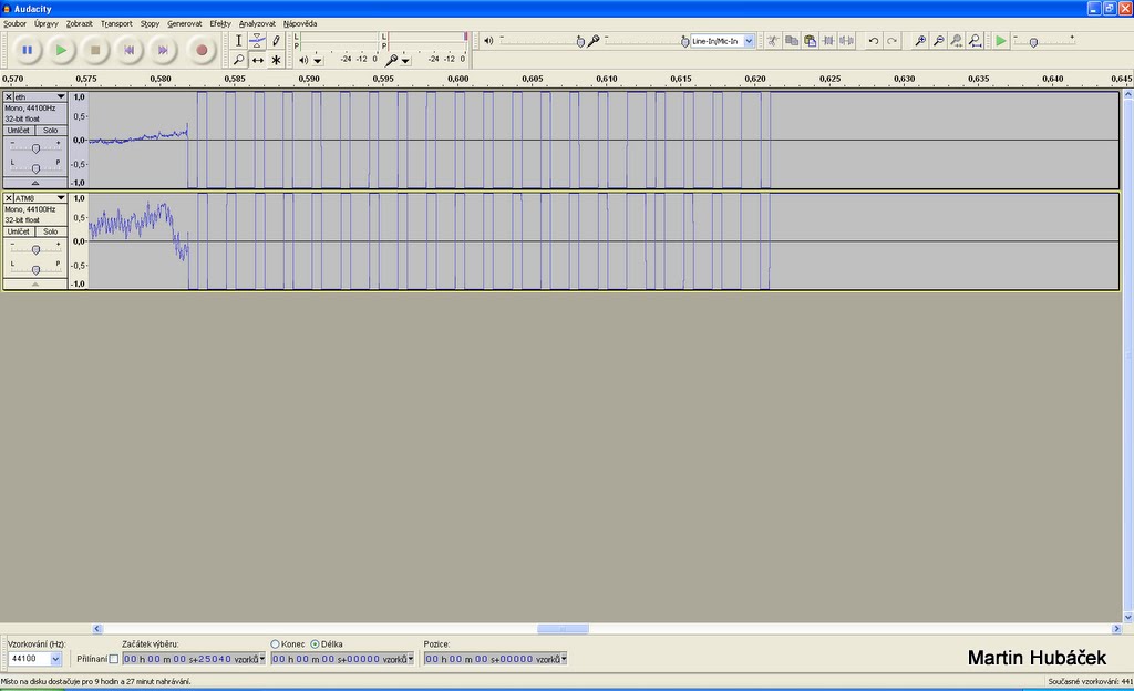
Let’s start to record some sound.. eh, data. Audacity is the best choice! The top wave-form is the original remote and the middle one wave-form is what I recreated with Arduino, later with plain ATmega168 chip (which is also Arduino anyway ;) ) Here’s the recorded “sound” @ 44100kHz (WARNING, dont play it directly but download it rather - loud sound!)
UPDATE
Hapilly I own RIGOL scope so here’s better image of signal and timing. Logic 1 means that the IR signal is emitted!
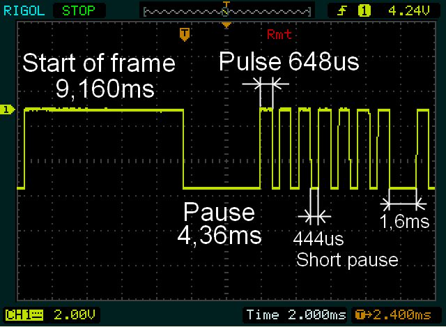
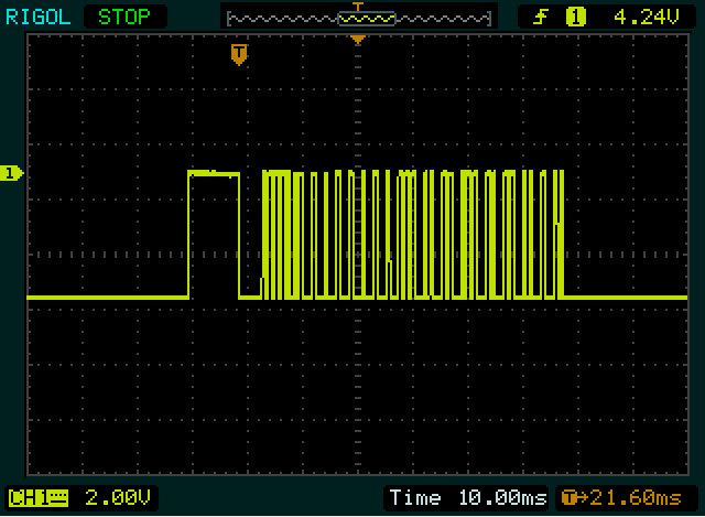
And view of the whole frame on my lowres screen ;)
The modulation frequency of infrared signal is 38kHz.
Now the remote worked perfectly, I’ve decoded all 8 buttons, there seems to be some sort of longer start pulse/bit, then some header and group of bits which changes with another button presses.
The entire code had longer start frame followed by 33 “bits”. The first 16bits were the same, the last 17 bits were different. Because I wanted to save the button code to 16 bits, I realized that the last bit was every time the same. So I called it “stop bit” :) So the first 16bits in code are saved in the constant, the other 16bits are sent to my routine by parameter and the last stop bit is hard-coded.
The library is also usable on the Arduino but it’s not wrote in wiring and needs some fiddling.
The code does not uses interrupts because I cannot use them in my final project. The signal is modulated with PWM, of course.
Here’s the header file, only two functions:
#define IR_STANDBY     0
#define IR_DVD         1
#define IR_CD         2
#define IR_MUTE     3
#define IR_GAME     4
#define IR_TV         5
#define IR_VOL_DOWN    6
#define IR_VOL_UP     7

#define IR_ON() DDRD=_BV(PIND6)
#define IR_OFF() DDRD&=~_BV(PIND6)

void ir_init();
void ir_send(unsigned char cmd);
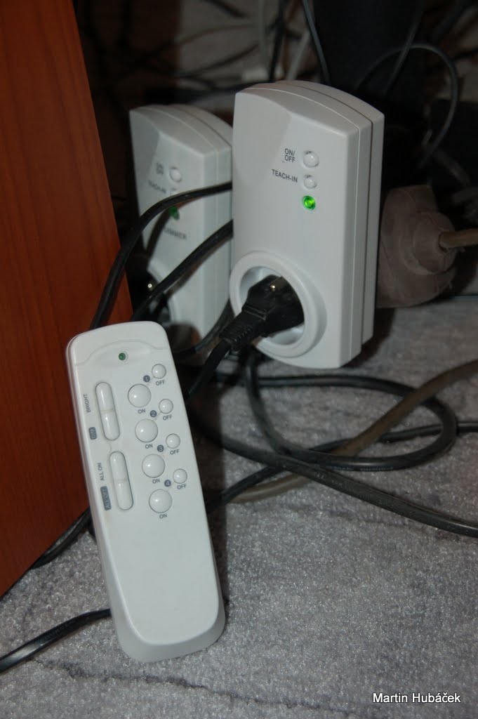
Adding an RF transmitter
In 2007 I bought 4 sets of this remote controlled home plugs. And now someone reverse engineered them. Perfect.. so I don’t have to :) But I had to anyway because I had to change the timing and rewrite slightly code to use loops instead of interrupts. Here’s the reverse engineered protocol by user “chr” on instructables. I rewrote the code and tuned it to 12,5MHz (25MHz from ENC28J60 divided by 2) instead of 12MHz which was used for V-USB software USB implementation in his original project.
After lot of playing I generated the same pulses as the remote. First line is the original RF remote, the second line is signal that I generated.
The header file rf.h:
void rf_send (uint16_t network, unsigned char payload);
void rf_init (void);
Nothing interesting here, in initialization is just command to set one pit as output.
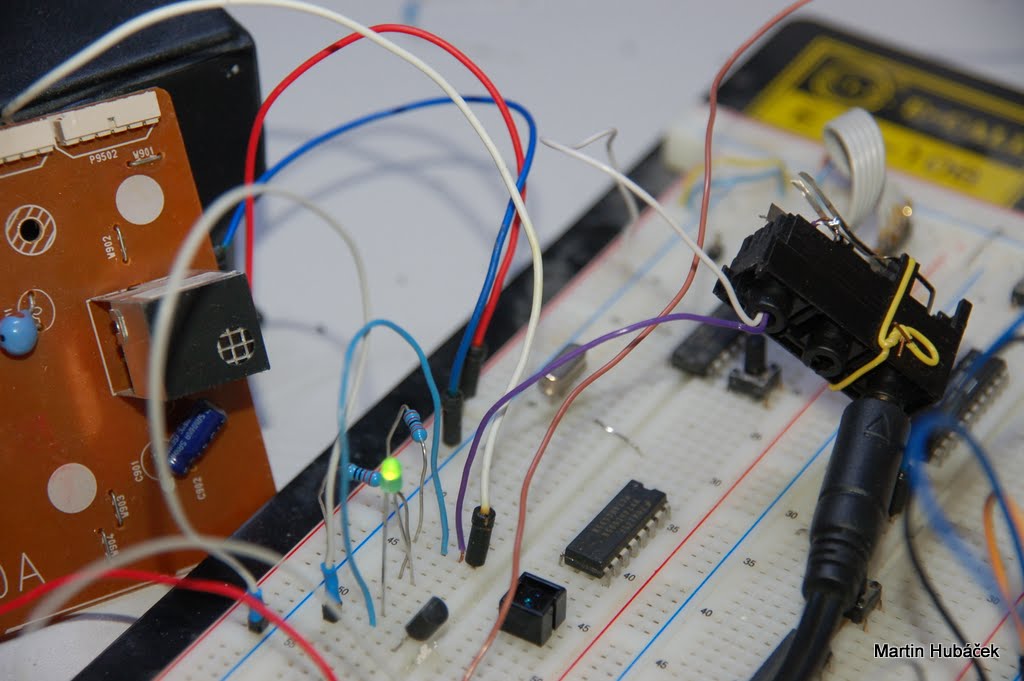
Putting it together
The entire project runs on my board, but I wrote the code as libraries and you can use it practically on any AVR.. It’s created for ATMega168. My board is using typical combination of ENC28J60 Ethernet controller and ATmega168. Schematics is the same like there on tuxgraphics page.
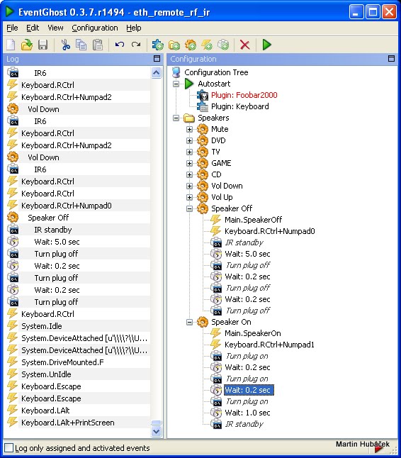
For automation and keyboard short-cuts I use EventGhost. Combination of right control button and numbers on numeric keyboard are now controlling my speakers. Ctrl+1 will turn on my remote - controlled plug, after 1 second is sent IR signal turning on the speakers. If I press Ctrl+0 then is sent Stand-by IR signal, the volume knob is automatically turned fully left and after few seconds the remote controlled plug is turned of.
To send HTTP request to my module, I set EvetGhost to run application “curl” (Linux command line app for HTTP communication, also for windows) with different parameters.