Library for Evalbot with LM3S9B92 ARM Cortex-M3 processor.
I wanted to use I2CS1 module and set multiplex to work on pins PJ0 & PJ1 which are perfectly accessible in standard 2.45mm pitch. But I had no luck to initialize them so I tried to connect Wii Nunchuk to I2S0 module and pins PB2 & PB3. These pins are connected to audio codec so you have to be careful when using nunchuk and audio codec at the same time.
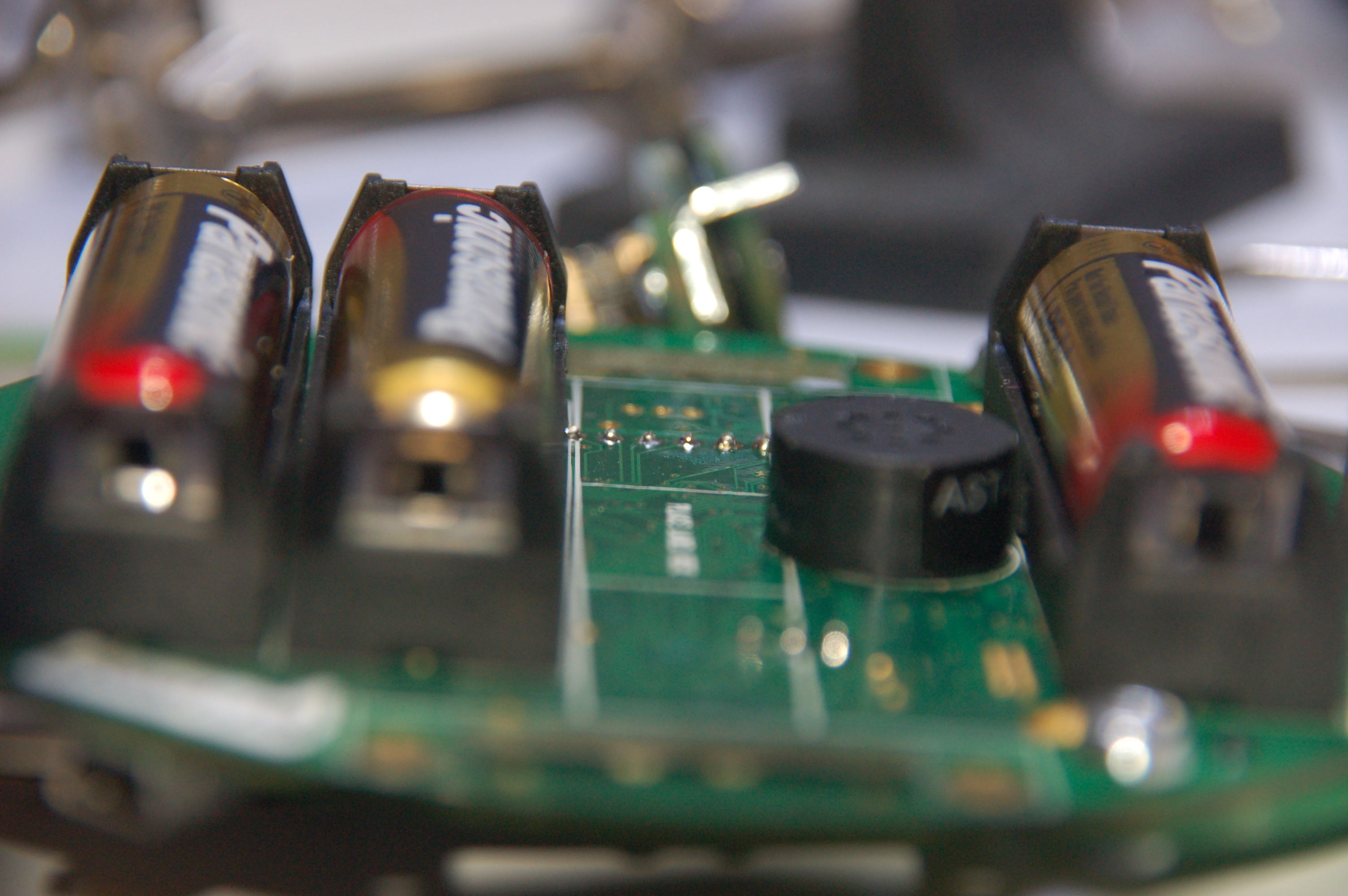
Near the codec are already pull-up resistors so you don’t have to put extra resistors. It’s also good place to solder wires if you don’t have the expansion connector. PB2 & PB3 are also on expansion connector but it’s hard to solder wires to it.
The I2C library is really simple and creates another layer of abstraction above StellarisWare. So you don’t have to think about how many bytes you want to send and if you have to use SINGLE transfer or BULK_START, BULK_CONT, BULK_FINISH..
Nunchuk lib
Only two functions. You have to init controller (it itself configures I2C bus) and then you periodically call nunchukcReadData() and after that, you have values in global variables. It’s all global I know, I could make class for this library but that’s nothing hard and it can be done by anyone :)
void nunchuckInit();
void nunchukReadData();

int joyX, joyY;
int accX, accY, accZ;
int btnC, btnZ;
I2C lib
clockSignalPin is constant that uniquely identifies module I2CS0 or I2CS1 and exactly pins that you want to connect to that I2C modules. So far only GPIO_PB2_I2C0SCL works now. It means that you want I2C bus with ICS0 module and you want the clock pin on PB2. The SDA pin is on PB3 in this case.
void I2CInit(int clockSignalPin);
void I2CWriteData(int peripheral, int address, char* data, int numberOfBytes);
int I2CReadData(int peripheral, int address, char* data, int numberOfBytes);
peripheral parameter can be for example I2C0_MASTER_BASE
Powering Nunchuk
The 3.3V is perfect for nunchuk. You have to solder pinhead connectors to the board. If you start to solder, you’ll see that the motor can short circuit the soldered pins. So I put some paper and black tape around the motor and hope that it will be ok.
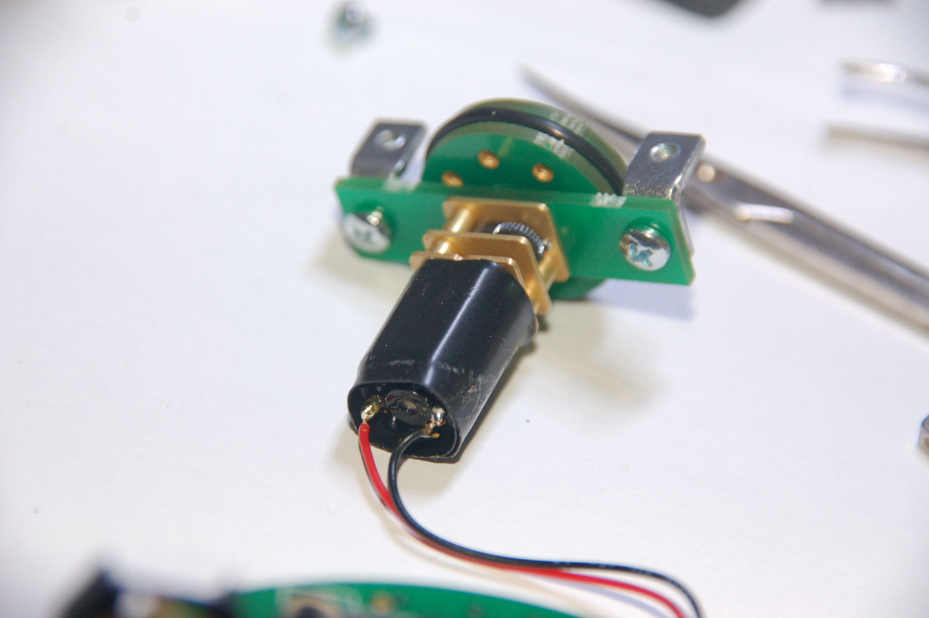
I cut the pins on the back side after soldering to avoid contact with motor.
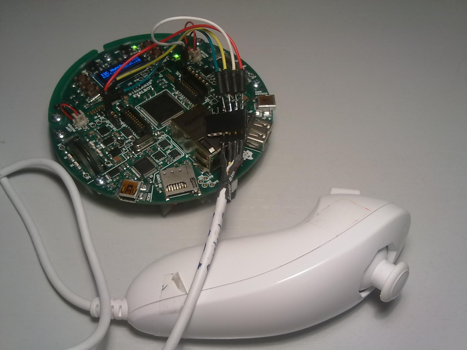
Here we are. We can use 3.3V power and some GPIOs for future projects!
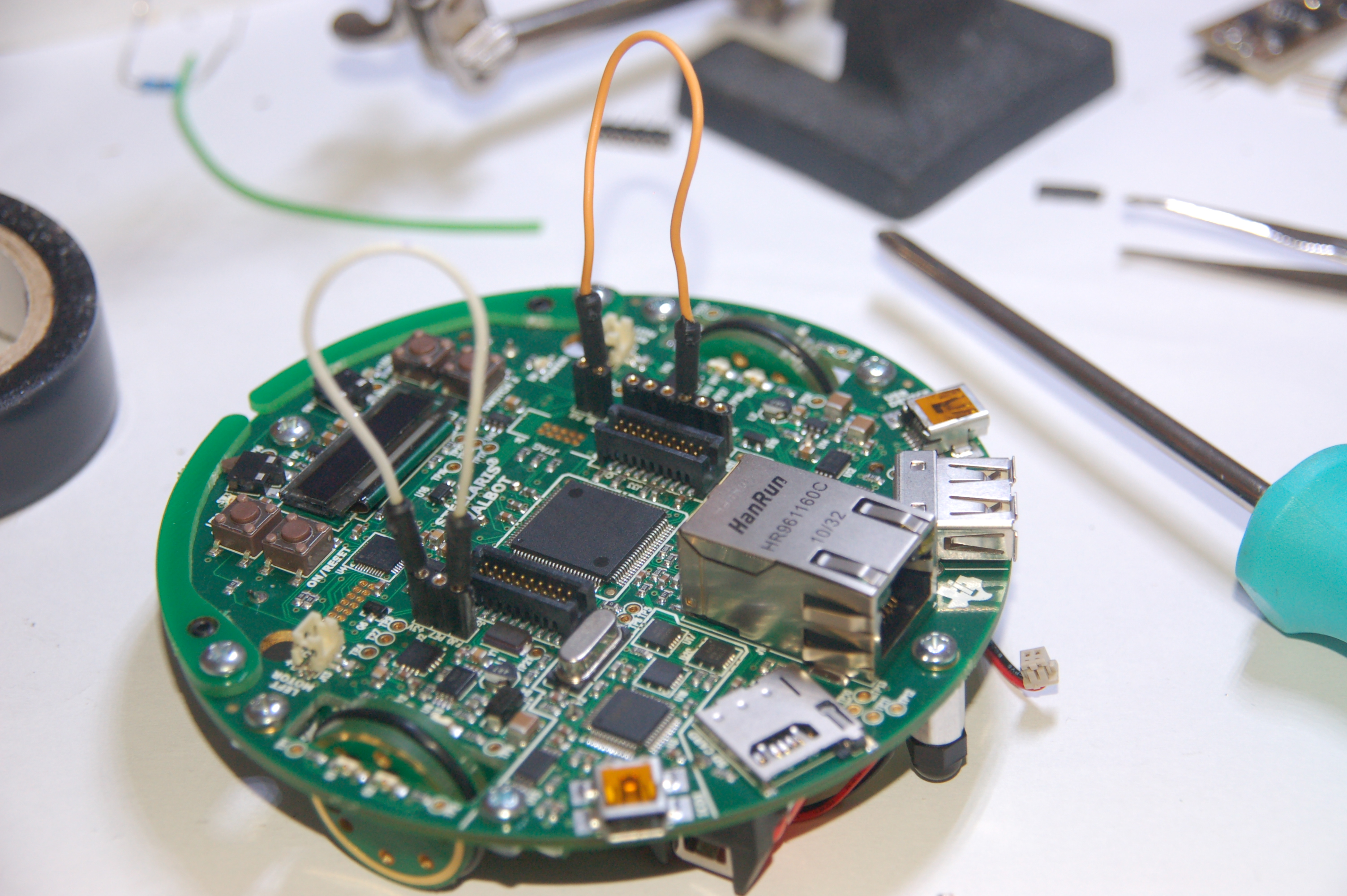
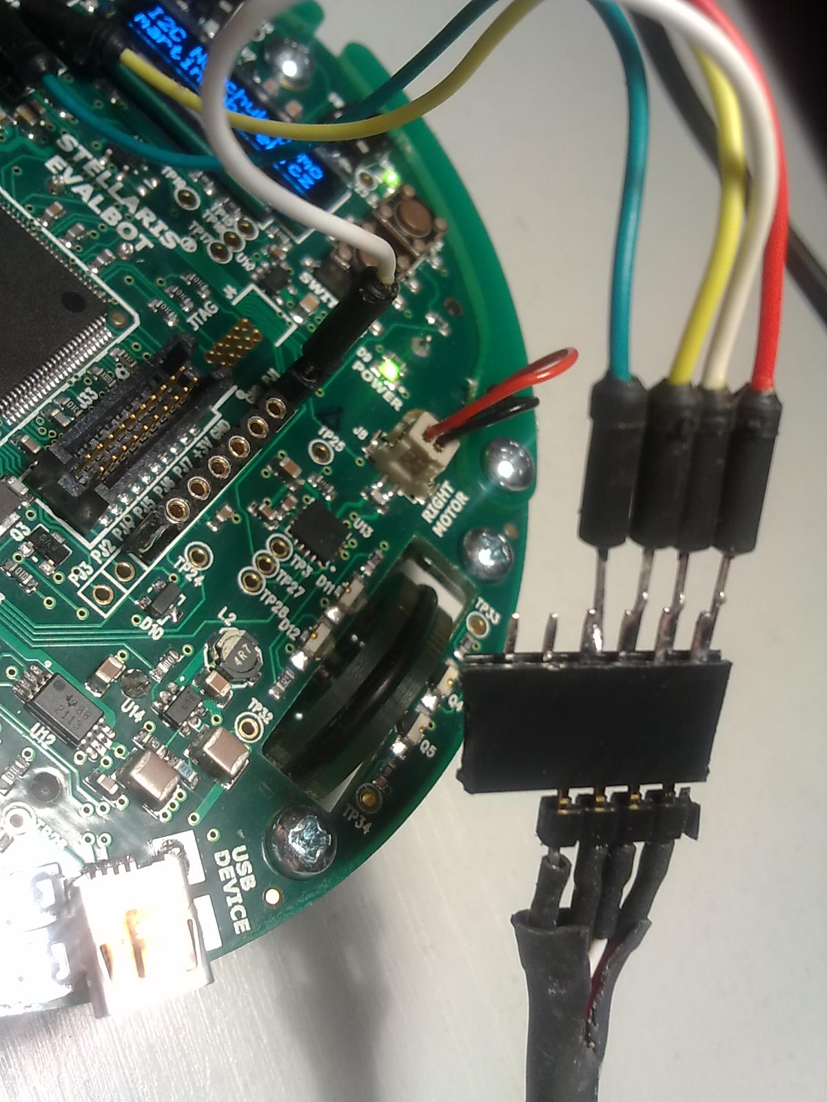
Connecting the SCLK and SDA
The yellow wire is SCLK and the green wire is SDA.
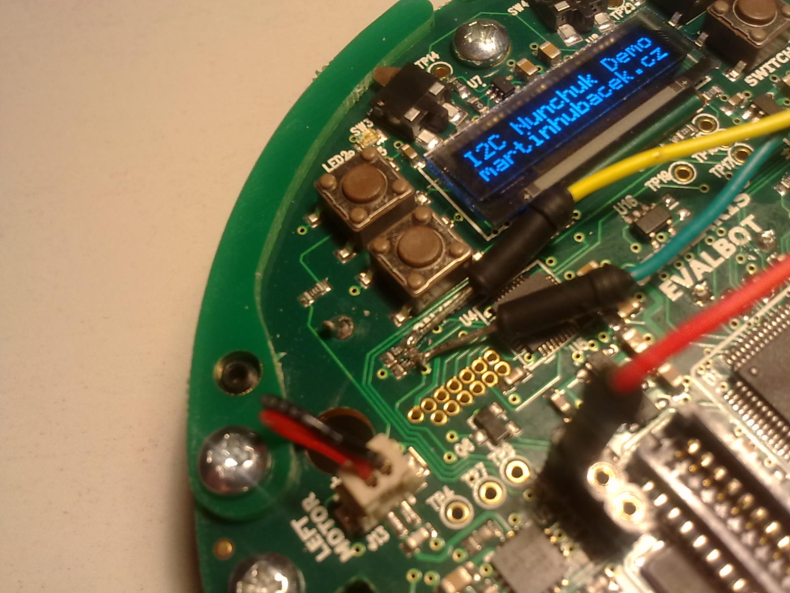
The colors of the connected wires on the picture bellow are exactly the same like colors that the original Nunchuk have.
| Color | Signal |
|---|---|
| RED | 3.3V |
| WHITE | GND |
| YELLOW | SCLK |
| GREEN | SDA |