
I have tinyFPGA BX dev board which I used to test open-source YOSYS and IceStorm tools. I also liked an awesome gui IceStudio that is multi-platform and installed everything to your system thanks to APIO package/tools manager.
I also sucesfully tried to create RISC-V system with picosoc example.
After a year or so, I wanted to test LiteX project again. Last time I had some issues to get it working. This time I suceeded. This blogpost is more like backup of what I did in case I would like to get Litex working again.
Note: You can find other photos/video and info also in my tweets here and there.
LiteX installation
LiteX needs some other tools for TinyFPGA. I use Ubuntu and downloaded:
Tools
- YosysHQ for synthesis
- RISC-V compiler for code. (I installed it manually, since I had issues with automatic download, more below.)
Then I added bin folders to my $PATH. I use ZSH bash so ~/.zshrc
export PATH="$HOME/dev/fpga/oss-cad-suite-linux-x64-20211213/oss-cad-suite/bin:$PATH"
export PATH="$HOME/dev/fpga/riscv64-unknown-elf-gcc-8.3.0-2019.08.0-x86_64-linux-ubuntu14/bin:$PATH"
LiteX
For LiteX I followed their official update README. I had some issues to install RISC-V toolchain with ./litex_setup.py --gcc=riscv command, you might be more lucky.
LiteX installation downloads bunch of things to the same directory where your install script is located, so create a new folder for that.
TinyProg
For flashing TinyFPGA BX you need to install tinyProg.
LiteX project synthesis/compilation
LiteX creates the gateware and software. You then load the binaries to the right place in the tinyFPGA SPI FLASH. I had first some issues with bad boot flash offset, but my fix have been already merged.
The most important things are in these files:
- platforms/tinyfpga_bx.py where pin definitions are set
- targets/tinyfpga_bx.py where the complete system is described together with SPI flash.
In your LiteX root directory you run
python3 litex-boards/litex_boards/targets/tinyfpga_bx.py --build --cpu-variant=lite
You need to specify --cpu-variant=lite to fit all to the FPGA.
This command creates the memory regions, compiles very useful simple serial command line firmware and then it starts to synthetize all the gateware.
The output is in the build/tinyfpga_bx directory. There are two folders.
gatewarewhere the bitstream for your FPGA is generated in thetinyfpga_bx.binfilesoftwarewhere the bios serial interface firmware is compiled tobios.bin
Preparing serial converter
Because TinyFPGA does not have usb to serial converter. You need to connect one with 3.3 V levels
- UART TX pin to tinyFPGA pin 2
- UART RX pin to tinyFPGA pin 1
You can open this serial console using one of these tools
picocom -b 112500 /dev/ttyUSB0- or
litex_term /dev/ttyUSB2
With these console terminals you will see also nice colours used by the console.
Uploading all to the FPGA
You use tinyProg
tinyprog -p build/tinyfpga_bx/gateware/tinyfpga_bx.bin -u build/tinyfpga_bx/software/bios/bios.bin
after FPGA loads the new bitsream you will see basic BIOS console
        __   _ __      _  __
       / /  (_) /____ | |/_/
      / /__/ / __/ -_)>  <
     /____/_/\__/\__/_/|_|
   Build your hardware, easily!

 (c) Copyright 2012-2021 Enjoy-Digital
 (c) Copyright 2007-2015 M-Labs

 BIOS built on Dec 19 2021 20:37:28
 BIOS CRC passed (6b954eb9)

 Migen git sha1: 9a0be7a
 LiteX git sha1: 92f5a9f0

--=============== SoC ==================--
CPU:            VexRiscv_LiteDebug @ 16MHz
BUS:            WISHBONE 32-bit @ 4GiB
CSR:            32-bit data
ROM:            32KiB
SRAM:           8KiB
FLASH:          1024KiB

--========== Initialization ============--

Initializing AT25SF081 SPI Flash @0x80000000...
SPI Flash clk configured to 8 MHz
Memspeed at 0x80000000 (Sequential, 4.0KiB)...
   Read speed: 812.3KiB/s
Memspeed at 0x80000000 (Random, 4.0KiB)...
   Read speed: 309.5KiB/s

--============== Boot ==================--
Booting from serial...
Press Q or ESC to abort boot completely.
sL5DdSMmkekro
Timeout
No boot medium found

--============= Console ================--

litex>
type help to see various memory commands.
Adding WS2812 LED peripheral
The best example how to add some hardware peripheral is WS2812 smart LED strip.
Hardware
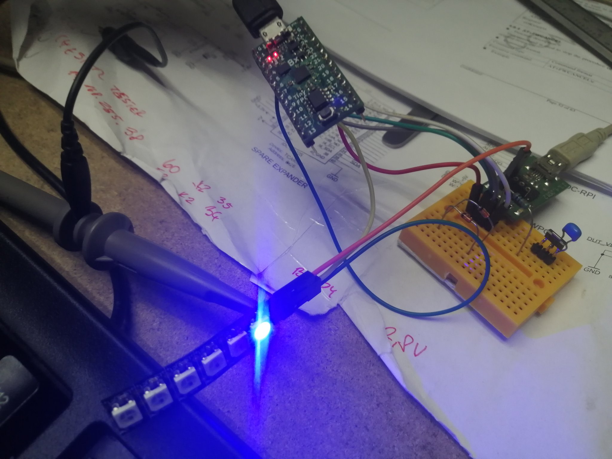
The WS2812 is 5V device, but if you connect just few of them to the 3V power supply, drive it with 3V signals and do not turn them all to full brightness, it will work for a test. If you power WS2812 with 5V, you might have issues since 3V data signal is too low for WS2812 to send high (logic 1) logic level. So that’s why I use 3V to power them for test.
- WS2812 + connected to tinyFPGA 3.3V pin
- WS2812 - connected to tinyFPGA GND pin
- WS2812 data connected to tinyFPGA 3 pin
Improve gateware
First import WS2812 in the begining of your ‘targets/tinyfpga_bx.py’ python file.
from litex.soc.cores.led import LedChaser, WS2812
I added WS2812 support right after the LED chaser effect (which is not chasing, but just blinking with the single LED on the TinyFPGA).
        # Leds -------------------------------------------------------------------------------------
        if with_led_chaser:
            self.submodules.leds = LedChaser(
                pads         = platform.request_all("user_led"),
                sys_clk_freq = sys_clk_freq)

        self.submodules.ws2812 = WS2812(platform.request("ws2812"), nleds=4, sys_clk_freq=sys_clk_freq)
        self.bus.add_slave(name="ws2812", slave=self.ws2812.bus, region=SoCRegion(
            origin = 0x2000_0000,
            size   = 4*4,
        ))
This added 4 LEDs and set peripheral addres to 0x20000000.
But we also need to edit our platforms/tinyfpga_bx.py file, so our gateware and mainly platform.request("ws2812") will know, where the LED pin is.
I added this to the platform right after # Leds definition.
_io = [
    # Clk / Rst
    ("clk16", 0, Pins("B2"), IOStandard("LVCMOS33")),

    # Leds
    ("user_led", 0, Pins("B3"), IOStandard("LVCMOS33")),

    # ws2812
    ("ws2812", 0, Pins("B1"), IOStandard("LVCMOS33")),
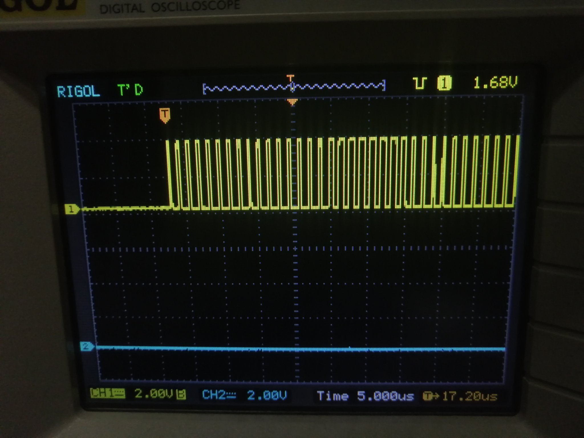
Now if you rebuild and upload gateware and software. You might see nothing, or a nice WS2812 bitstream if you connect oscilloscope to pin 3.
The great thing is that BIOS allows us to read and write memory from the terminal. So we can easily test peripherals even without proper code.
To set first LED to:
- green type
mem_write 0x20000000 0x100000 - red type
mem_write 0x20000000 0x001000 - blue type
mem_write 0x20000000 0x000010
The second LED has address offset of 0x04 so type mem_write 0x20000004 0x100000 to set second LED to green.
Demo firmware
Now I wanted custom firmware project, not just BIOS. So I looked around and there is a demo project in the litex/litex/soc/software/demo/.
To create a demo based on your currently generated SOC with WS2812 memory mapped type litex_bare_metal_demo --build-path=build/tinyfpga_bx and the demo is copied to your root project folder and compiled. Thanks to the --build-path=build/tinyfpga_bx the firmware will exactly know the registers and memory regions for the generated SOC.
Also check the build/tinyfpga_bx/software/include/generated folder, there are some useful files to understand how the memory mapping looks regions.ld
MEMORY {
	sram : ORIGIN = 0x10000000, LENGTH = 0x00002000
	spiflash : ORIGIN = 0x80000000, LENGTH = 0x00100000
	rom : ORIGIN = 0x80050000, LENGTH = 0x00008000
	ws2812 : ORIGIN = 0x20000000, LENGTH = 0x00000010
	csr : ORIGIN = 0xf0000000, LENGTH = 0x00010000
}
And in mem.h you can see our WS2812 peripheral and its address
#ifndef WS2812_BASE
#define WS2812_BASE 0x20000000L
#define WS2812_SIZE 0x00000010
#endif
Linker edits
Because tinyFPGA does not have initialized main RAM to save LUTs (called main_ram in the linker) where the code will run, we need to change demo/linker.ld code a bit.
Replace all occurrences of main_ram with rom.
Now you can recompile and upload the demo firmware, it should boot
(I use this ugly command in my makefile to run make in the demo directory, copy it with the brackets ( and ))
(cd demo && SOC_DIRECTORY='../litex/litex/soc' BUILD_DIR=../build/tinyfpga_bx make)
and flash demo
tinyprog -u demo/demo.bin
You get a similar console like in BIOS. Try donut renderer :)
LiteX minimal demo app built Dec 23 2021 22:19:00

Available commands:
help               - Show this command
reboot             - Reboot CPU
led                - Led demo
donut              - Spinning Donut demo
helloc             - Hello C
litex-demo-app>
Adding WS2812 control
Now we add support for our new WS2812 peripheral.
Include the memory map in main.c
#include <generated/mem.h>
Then replace led_cmd with this function:
#ifdef CSR_LEDS_BASE
static void led_cmd(void)
{
	int i;
	printf("WS2812 demo...\n");

	uint32_t *ws2812 = WS2812_BASE;

	for(i=0; i<32; i++) {
		*ws2812 = 0x100000;
		busy_wait(500);
		*ws2812 = 0x001000;
		busy_wait(500);
		*ws2812 = 0x000010;
		busy_wait(500);
	}
}
#endif
This code might be rewritten better, I know. But it does the work.
Recompile, reload
(cd demo && SOC_DIRECTORY='../litex/litex/soc' BUILD_DIR=../build/tinyfpga_bx make)
sudo tinyprog -u demo/demo.bin
Now type led in the serial console and you get blinking WS2812 LED. Congratulations!