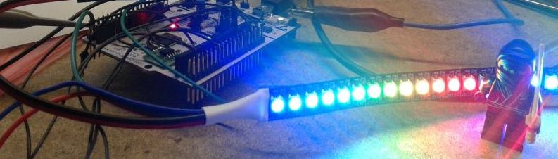
I needed to drive WS2812B RGB LED or NeoPixel strips from my MCU. I quite like and use STM32 so at first I looked around for existing solutions. There are a few ways to driver LEDs. Since I’m familiar and experienced with DMA I prefered solutions which would lower the CPU load. I will write about pros and cons of different approcaches based on my own needs.
Someone else can find different methods more interesting. Also there are different aspects like how efficiently you use RAM. Whether the real RGB frame buffer is pre-computed or you generate specific waveforms on the fly. Scaling is also important if you would need more strips connected to different MCU ports.
Below you will find some theory and decisions I’ve made during development.
Final WS2812b libraries with some more README explanation is on my GitHub
There is a few efficient methods to drive these WS2812B LEDs.
DMA > SPI/I2S peripheral
You use only MOSI signal from MCU. You select appropriate clock speed for this peripheral so the waveform of MISO could generate necessary “0” and “1” bits. Then you create buffer with this specific bit patterns and you command the DMA to send that buffer to SPI->TX register.
- + very precise timing
- - cannot be scaled if you need more than 4 strips that are not connected in series
DMA > TIMer Output compare register
You set DMA that will copy pre-computed value from memory to TIMer output compare register. This transfer will occur every period with TIMx_UP event. So next period the output compare will change the PWM cycle to go low in different time from the begining. You are basicly changing duty cycle of the PWM. The advantage is that you can use the same timer to generate PWM waveform and trigger the next DMA transfer.
This method is used by Daedaluz library: https://github.com/Daedaluz/stm32-ws2812
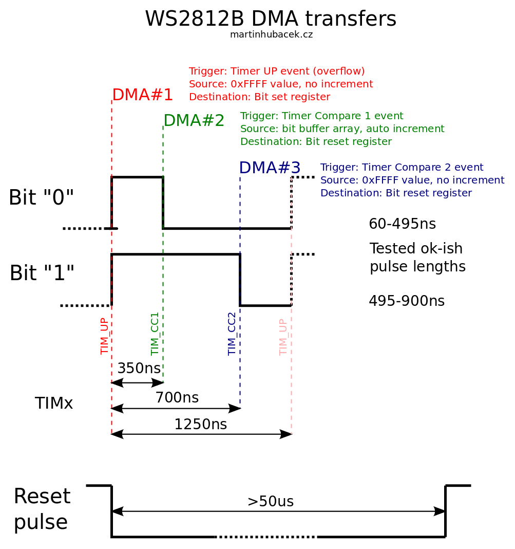
TIMer > DMA > GPIO
This is I think the most complicated method but it can easily be scaled. It involves some jitter in generated signal but this jitter is way below the specification of WS2812B driving signals. It works like this. You have one TIMer which has period 1.25us. Then you use two output compare registers from the timer. One to create a shorter pulse for “0” bit and second compare register for longer “1” bit. Then you set three DMA channels. All DMAs will write directly to GPIO output register. First DMA will be triggered by TIMx_UP (overflow) event and sets GPIO output pins to HIGH. Then the second DMA will be triggered by output compare one and will drive the GPIO output signal LOW in case you need send “0” bit to the LED strip. Then the third DMA will be triggered by compare two and will drive all GPIO output signals to LOW no matter if the pin is in HIGH or already logic LOW value.
Since the STM32 has 16bit ports. You can control up to 16 LED strips. There is one limitation but we can get get around. Because we are writing to the whole 16 bit port we can’t use any other pin from this port even if we use only one output for our LED strip. The DMA will write to GPIO output data register and will overwrite all unused bits. Fortunately almost every ARM vendor has in his GPIO peripheral register register we can take advantage of. It’s usually called “bit set” or “bit reset” register. This register is used to improve old “read-modify-write” behavior. With these you can atomically change one bit of the port without affecting the others. Now you have to only change that three DMAs to write to destinations to these registers and generate one, five or sixteen waveforms for WS2812 LED strips.
My first version of library was developed on STM32F100. This bit older chip can run at maximum 24Mhz. During development the library worked fine, but when I turned on SysTick and UART Rx interrupts I had some jitter on WS2812B signal and blinking LEDs even when they have been turned off (to the “black” color).
I noticed that it behaves strangely when I have GPIO_SetBits() for debuging purporse in my DMA transfer complete interrupt. On the scope I could see that one bit for LED strip don’t have either “0” or “1” duty cycle. It was something in between. The reason was that the CPU in my DMA transfer complete interrupt routine was accessing APB1 bus in the moment the DMA would also write on the APB1 bus to the GPIO peripheral. There’s simple arbitration in the STM32 and when CPU and DMA is accessing the same bus, they are alternating. I checked that my core and peripheral bus is running at maximum. What next? What will happen if I overclock the MCU from maximal 24Mhz frequency? I switched PLL to generate 32MHz and really the problematic pulse gets shorter. Moreover all the “0” bits gets shorter DUTY+ cycle. So i was running at the edge with 24MHz. When I turned on SysTick which is accessing also GPIOs to read the buttons, some LEDs again flickers. So I changed the MCU speed to 40MHz and now it’s ok. I have 30ns reserve in the worst case then CPU is accessing APB1 bus and DMA wants that access too.
So the conclusion is that I have to use more present Cortex-M like 48MHz STM32F0x CM0 or STM32F4 CM4. Also I think that this newer MCUs have improved multilayer AHB/APB bus so the CPU/DMA arbitration could work more efficiently.
Future improvements
In case I will drive really lot of LEDs. I will need image frame buffer and then another big buffer with pre-computed bit variations for DMAs. If you have less RAM this approach will be inefficient or impossible. So my next version will have on-the-fly generation of DMA data buffer based on image frame buffer. The way it will work is that I first prepare bit buffer for one or few LEDs and start the DMA transfer. Then I use the DMA Half-Transfer interrupt and in this interrupt I copy more data from image buffer to the LED bit buffer. In the DMA transfer complete I update the second half of the LED bit buffer over again.
There will be more CPU utilization of course but I gain more RAM. This needs to be explored.
Update 1.10.2016: Moving to a faster/newer STM32F Cortex-M4 device with few improvements
so I’ve implemented improvements above and created internal bit-buffer which is updated in IRQ on-the-fly.
One separate buffer for your (big) framebuffer and second internal bitbuffer for DMA
RGB framebuffer - this is one dimension array with {R1, G1, B1, R2, G2, B2, …} format. Bitbuffer - this is basicaly the same format buffer like the Octo2811 lib uses but it is allocated only for 2 LEDs (2 LEDs on each of 16 output channels)
Here is the improvement. I fill the bitbuffer on-the-fly in the double-buffering fashion based on DMA_HALF_TRANSFER and DMA_COMPLETE_TRANSFER interrupts. While the data to the first LED is fed, I prepare the next 24 bits in the second part of the bitbuffer for the second LED in the DMA Irq handler in the background. This IRQ bit-juggling was optimized so it’s just a small overhead - I’ll explain that down below. And while the data from the second part of bitbuffer is send to the second LED, the DMA Half transfer interrupt is fired and in it are prepared another 24 bit data for first LED.
Bit-banding for bit-juggling in the IRQ
Interrupts has to be very fast. Thats why I tried many ways to “serialize” the bits from framebuffer to bitbuffer. The best solution is to use bit-banding (don’t confuse with bit-banging). This is HW accelerated access to single bits in RAM and I’ve made a practical video some time ago.\
Because the bits are computed on the background during the transmission, there is little CPU overhead. For one LED strip it is on 64MHz STM32F3 just about 8% only during transmission of the data. The overhead is bigger as you use more parallel LED strips on the same port. It can be like 10% for two LEDs but it don’t rise linearly. You have to take into account overhead of IRQ service routine, clearing IRQ bits. The bit-juggling with bit-banding implementation is quite efficient.
Bit-banding can also improve the speed of set pixel function in the OctoWS2811 library. If you try that let me know.
I had also fun with logical ANDing/ORing two LED strips into the third one. It is in the video below
The same method is also used here:
- https://github.com/PaulStoffregen/OctoWS2811
- https://github.com/g4lvanix/0xWS2812
- http://mcuoneclipse.com/2015/08/05/tutorial-adafruit-ws2812b-neopixels-with-the-freescale-frdm-k64f-board-part-5-dma/
Interesting timing experiments with WS2812B
https://cpldcpu.wordpress.com/2014/01/14/light_ws2812-library-v2-0-part-i-understanding-the-ws2812/
Another WS2812B timing troubleshooting and hand-crafted PIC assembly
http://hypnocube.com/2013/12/design-and-implementation-of-serial-led-gadgets/